- 您现在的位置:买卖IC网 > Sheet目录3828 > ATMEGA169P-16MCU (Atmel)MCU AVR 16K ISP FLSH 16MHZ 64QFN
2005 Microchip Technology Inc.
Preliminary
DS41265A-page 195
PIC16F946
16.3.3
BROWN-OUT RESET (BOR)
The BOREN0 and BOREN1 bits in the Configuration
Word register selects one of four BOR modes. Two
modes have been added to allow software or hardware
control of the BOR enable. When BOREN<1:0> = 01,
the SBOREN bit (PCON<4>) enables/disables the
BOR allowing it to be controlled in software. By select-
ing BOREN<1:0>, the BOR is automatically disabled in
Sleep to conserve power and enabled on wake-up. In
this
mode,
the SBOREN
bit
is
disabled.
See
Register 16-1 for the Configuration Word definition.
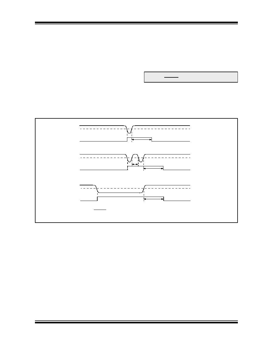
If VDD falls below VBOR for greater than parameter
tions”), the Brown-out situation will reset the device.
This will occur regardless of VDD slew rate. A Reset is
not insured to occur if VDD falls below VBOR for less
than parameter (TBOR).
On any Reset (Power-on, Brown-out, Watchdog Timer,
etc.), the chip will remain in Reset until VDD rises above
be invoked, if enabled and will keep the chip in Reset
an additional 64 ms.
If VDD drops below VBOR while the Power-up Timer is
running, the chip will go back into a Brown-out Reset
and the Power-up Timer will be re-initialized. Once VDD
rises above VBOR, the Power-up Timer will execute a
64 ms Reset.
FIGURE 16-3:
BROWN-OUT SITUATIONS
Note:
The Power-up Timer is enabled by the
PWRTE bit in the Configuration Word.
64 ms(1)
VBOR
VDD
Internal
Reset
VBOR
VDD
Internal
Reset
64 ms(1)
< 64 ms
64 ms(1)
VBOR
VDD
Internal
Reset
Note 1:
64 ms delay only if PWRTE bit is programmed to ‘0’.
发布紧急采购,3分钟左右您将得到回复。
相关PDF资料
AT91SAM7XC256-CU
MCU ARM 256K HS FLASH 100-TFBGA
PIC16LF874A-I/P
IC MCU FLASH 4KX14 EE A/D 40DIP
PIC16F84-10/SO
IC MCU FLASH 1KX14 EE 18SOIC
AT91SAM7XC128-CU
MCU ARM 128K HS FLASH 100-TFBGA
PIC18F2458-I/SO
IC PIC MCU FLASH 12KX16 28SOIC
PIC18F4455-I/P
IC PIC MCU FLASH 12KX16 40DIP
AT91SAM7X256-CU
MCU ARM 256K HS FLASH 100-TFBGA
PIC16C73B-20/SS
IC MCU OTP 4KX14 A/D PWM 28SSOP
相关代理商/技术参数
ATMEGA169P-16MU
功能描述:8位微控制器 -MCU AVR 16K FLASH 512B EE 1K SRAM LCD ADC RoHS:否 制造商:Silicon Labs 核心:8051 处理器系列:C8051F39x 数据总线宽度:8 bit 最大时钟频率:50 MHz 程序存储器大小:16 KB 数据 RAM 大小:1 KB 片上 ADC:Yes 工作电源电压:1.8 V to 3.6 V 工作温度范围:- 40 C to + 105 C 封装 / 箱体:QFN-20 安装风格:SMD/SMT
ATMEGA169P-16MU SL383
制造商:Atmel Corporation 功能描述:MCU 8BIT ATMEGA RISC 16KB FLASH 3.3V/5V 64PIN MLF - Tape and Reel
ATMEGA169P-16MUR
功能描述:8位微控制器 -MCU AVR LCD 16KB FLSH EE 512B 1KB SRAM-16MHZ RoHS:否 制造商:Silicon Labs 核心:8051 处理器系列:C8051F39x 数据总线宽度:8 bit 最大时钟频率:50 MHz 程序存储器大小:16 KB 数据 RAM 大小:1 KB 片上 ADC:Yes 工作电源电压:1.8 V to 3.6 V 工作温度范围:- 40 C to + 105 C 封装 / 箱体:QFN-20 安装风格:SMD/SMT
ATMEGA169P-8AU
制造商:ATMEL 制造商全称:ATMEL Corporation 功能描述:Microcontroller with 16K Bytes In-System Programmable Flash
ATMEGA169P-8MU
制造商:ATMEL 制造商全称:ATMEL Corporation 功能描述:Microcontroller with 16K Bytes In-System Programmable Flash
ATMEGA169PA
制造商:ATMEL 制造商全称:ATMEL Corporation 功能描述:8-bit Microcontroller with 16K Bytes In-System Programmable Flash
ATMEGA169PA_1
制造商:ATMEL 制造商全称:ATMEL Corporation 功能描述:High Endurance Non-volatile Memory segments
ATMEGA169PA-AN
功能描述:8位微控制器 -MCU AVR XMEGA 384KB 105C 4KB EE32K SRAM-16MHz RoHS:否 制造商:Silicon Labs 核心:8051 处理器系列:C8051F39x 数据总线宽度:8 bit 最大时钟频率:50 MHz 程序存储器大小:16 KB 数据 RAM 大小:1 KB 片上 ADC:Yes 工作电源电压:1.8 V to 3.6 V 工作温度范围:- 40 C to + 105 C 封装 / 箱体:QFN-20 安装风格:SMD/SMT